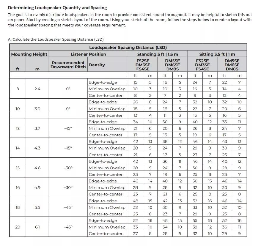
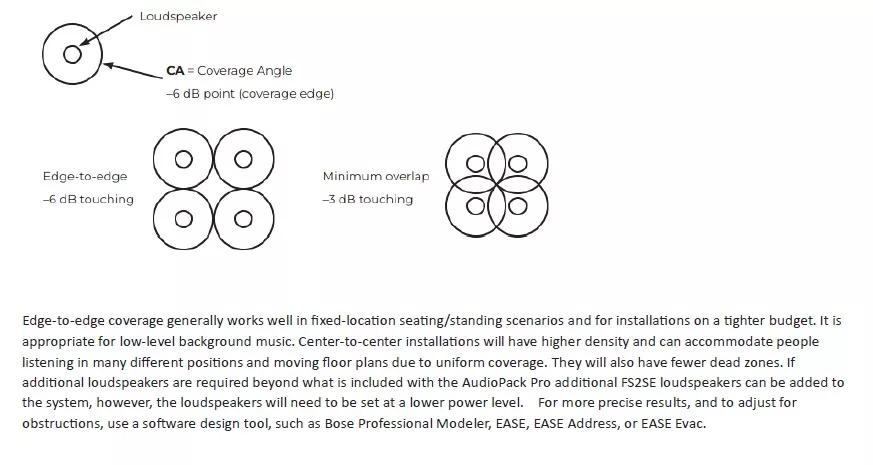
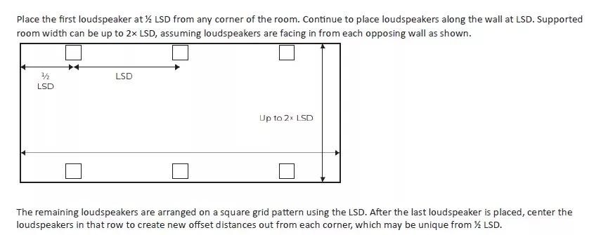
DESIGN : Planning Your Loudspeaker Locations
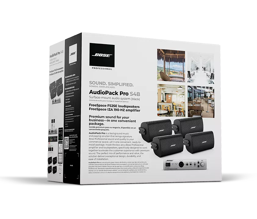
UNBOXING : Package Contents

PRE-INSTALL CHECKLIST : What You Will Need


MOUNTING & INSTALLING : Installation


FINAL STEPS : Additional Equipment, and Cleanup
